3D Printing and Scanning
Table of content:
1 - Individual Assignment1.1 - 3D Printing
1.1.1 - cage and disk 1.1.2 - cage and ball 1.1.3 - cage and ball V2
1.2 - 3D Scanning
1.2.1 - scanning with scanner 1.2.2 - scanning with meshroom
2 - Group assignment
Individual Assignment
3D Printing
Before jumping into the individual assignment, let me give you a brief description about 3D printing in general and the printer we are using
in our lab.
3D printing is one of the methods that comes under additive manufacturing. The printer ADDS the layers of filament on top of each other.
There are generally 4 motors used in 3D printers, 3 of them handles the XYZ axis movement and 1 of them handles the filament extrusion and
with the help of these 4 motors, a 3d model is created. You feed the filament into the nozzle of the 3D printer. The nozzle heats and melts
the filament. Then the nozzle, with the help of XYZ axis motor builds the model layer by layer with the molten filament. For adhesion, the
bed is also heated.
Advantages of 3D printing:
- 3D printing is a great tool for rapid prototyping.
- you can make almost any design in the 3D printer. If the object needs supports or raft/brim, there will be post process to it.
- 3D printer are quite cheap these days. You can get printers like Ender 3 for around 12K INR.
- 3D printing a model is cheap compare to the other manufacturing methods.
- there are wide variety of filaments in which you can print the models.
Limitations of 3D printing:
- it takes a lot of time to print a model.
- calibrating the 3D printer takes a lot of patience, if you don't calibrate your printer properly, it can show it's effect in your printed models.
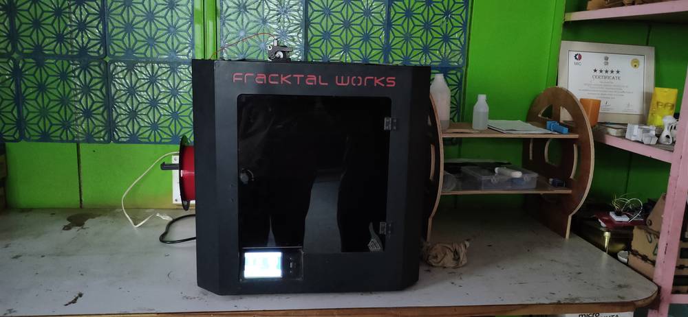
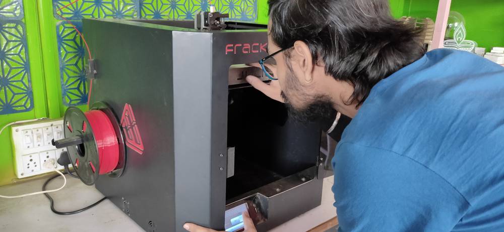
We have Fracktal Works’s Julia advance 3D printer. First we need to load the filament into the extruder through the filament run-out sensor.
What the filament run-out sensor does is that if in the middle of printing the spool runs out of filament or the filament breaks during the
print, the printer will pause the printing so that you can change/adjust the filament.
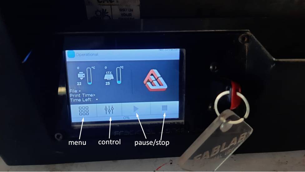
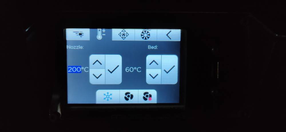
Here is how the control panel of the 3d printer looks like,
In the home section, you will see options like menu, controls, pause and stop.
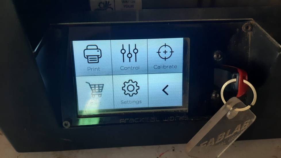
Inside the menu there are option like print where you can select the file you want to print from USB or locally, control where there will be a
bunch of options(the one in home and this one in the menu is the same), calibrate where you can calibrate the bed level, cart, settings and
back button. I have mostly used the print, control and calibrate options
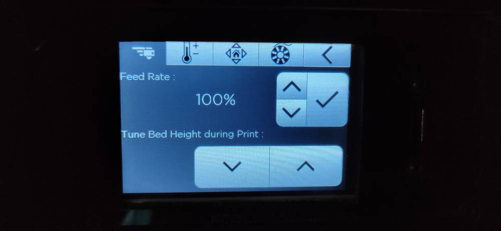
Inside the controls, there are options like feed rate where you can change the feed rate of the filament and tuning the bed level during the
print
Setting the nozzle and bed temperature beforehand
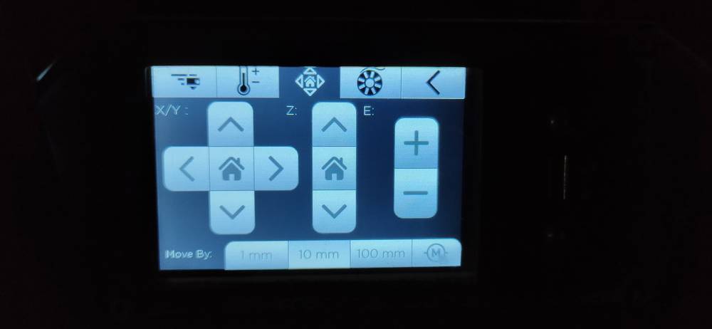
Moving the XYZ axis
Before printing, it is a good habit to calibrate the bed level. Calibrating bed level means that the distance between nozzle and the bed
should be as per your layer height and it should be uniform throughout the bed. Select “full calibrate” from the calibrate option and just
follow the instructions given in the display,
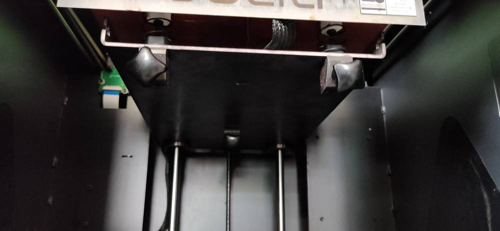
First you need to loosen all the screws under the bed
Then one by one, tight the screw of the corner where the nozzle will hover
Then the nozzle will hover at 9 different places onto the bed one by one. When the nozzle hovers over the bed, slide a piece of paper between
the nozzle and bed and move the paper back and forth. There should be very minimal friction when you move the paper. If the movement of paper
is very loose or tight, you can adjust the bed level through the up and down button while calibrating.
After the calibration is done, you are set to print your model. You can preheat the nozzle and bed before printing from the “control” menu.
However even if you directly select the print option, the printer will wait till the nozzle and bed reaches the set temperature and once it
reaches the temperature set in the gcode file, it will start printing.
For 3D printing, I am using fusion 360 as designing software(CAD) and I am using cura/fractory for slicing the model(CAM). Slicing basically
means that the CAM software converts the 3D model into the language that the machine understands so if you open the gcode file with notepad,
all you’ll see is bunch of coordinates for XYZ axis motor long with the speed and temperatures.
<<<---CAGE AND DISK--->>>
I had in my mind to make a cage like structure and put a coin inside which cannot be taken out of the cage. To do that, start printing the
cage and halfway through it, pause the print and put a coin inside and resume the print. Since the diameter of the coin is not large, I
thought the printer would be able to bridge the distance between one point of the cage to another without support.
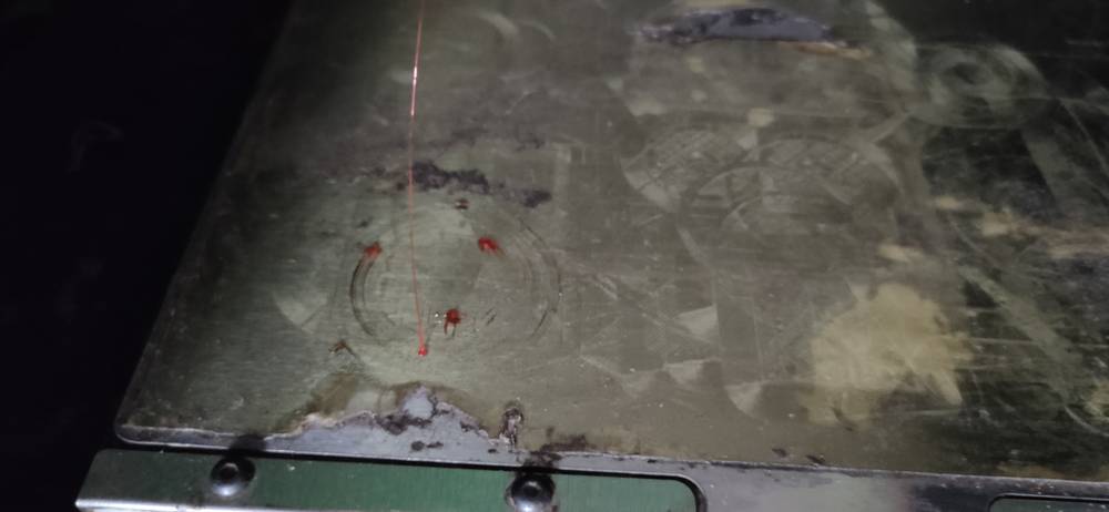
However, to test the strength of the printer in terms of making a bridge from one point to another without support, i designed a model in
fusion


For slicing I used cura and i set
210° nozzle temperature
60° bed temperature
20% infill
50ms printing speed
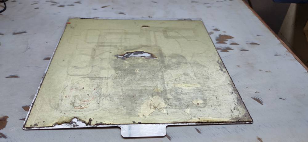
gave a raft for better adhesion,considering the condition of the bed
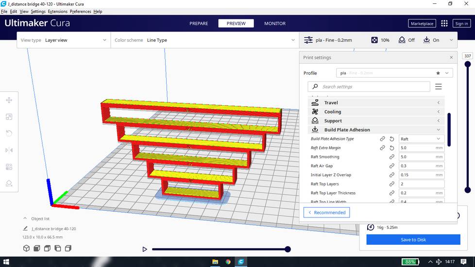
Using the PLA filament, here are the result
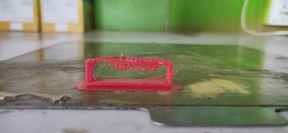
The printer was able to make a bridge for 20mm without support though
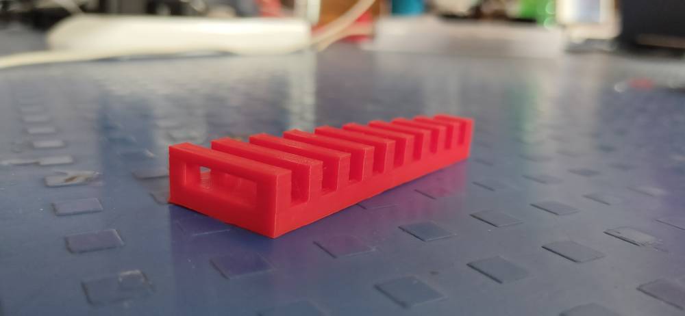
This is the ipad pro stand i printed at my home with Ender 3 with PLA filament with
200° nozzle temperature (initial 215° and later 200°)
60° bed temperature
20° infill
Skirt
Without support
50ms speed
and here are the result
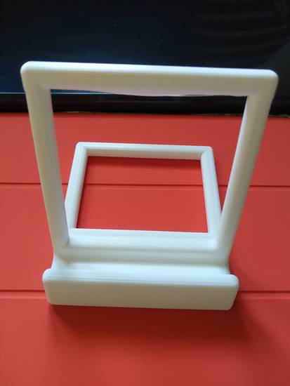
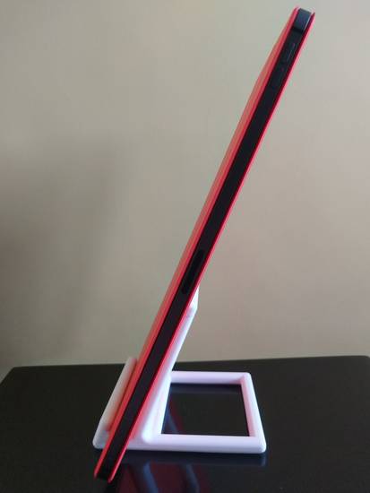
The distance between the two ends of the frame is 83mm. This is the reason I wanted to see how far the printer in our lab can make a bridge
without support. However, after seeing the results of the bridge test I dropped the idea of pausing the print and putting a coin because the
printer wasn’t able to print 40mm without support.
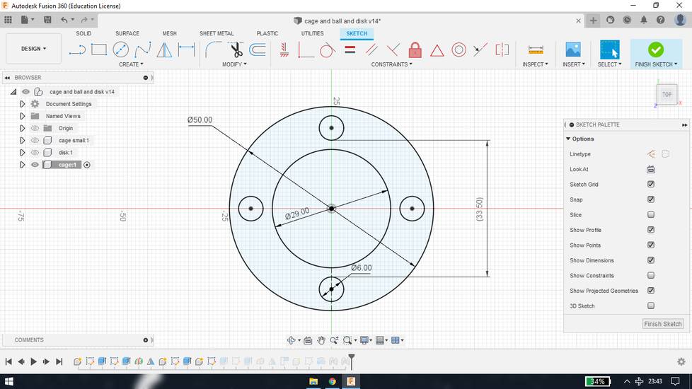
So i designed the cage as well as coin(ended up making a thick disk) in fusion
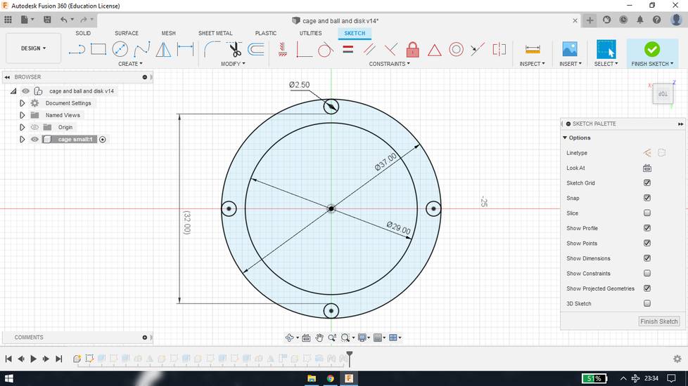
Pillar extrusion = 40mm
Top and bottom lid extrusion = 5mm
For slicing i used cura
210° nozzle temperature
60° bed temperature
20% infill
50ms speed
20% Support density
Support pattern grid

After the gcode file was ready, I calibrated the bed and started printing but the nozzle seemed too close to the bed so the filament wasn’t
coming out of the nozzle even though the extruder motor was rotating to push/retract the filament. I stopped the print and re-calibrated the
bed.
After re-calibrating I again put the model for print but again the nozzle was too close to the bed so the filament wasn’t coming out of the
nozzle. I repeated the calibrating-printing process for the same model at least 5 times and the model still won’t print because the nozzle was
too close to the bed.
Between calibrating-printing, things were happening to the printer like,
PLA was dripping from the nozzle like a syrup
Smoke was emitting from the nozzle
Note that during all these, the temperature for the nozzle was set at 210° (215° for the initial layer) in the slicer. I didn’t constantly
observe the temperature that was showing in the display of the printer but it was mostly 210°.
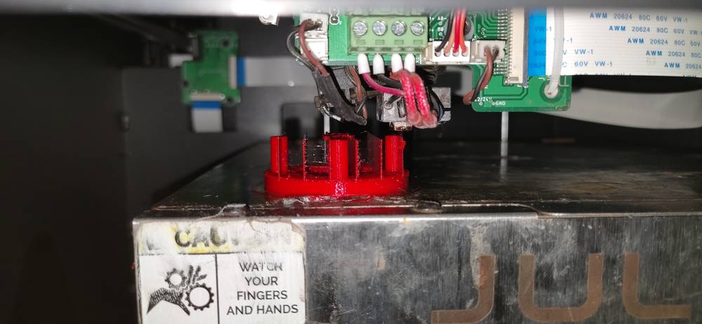
Then our instructor told us that students in the past had experienced similar issues with the cura software. Then I sliced the same STL file
in the software dedicated for this printer called fractory. Without calibrating the bed, i put the model for print and it printed fine at
last.

Here are the results,
After removingthe supports,
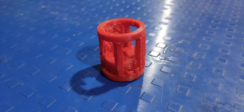
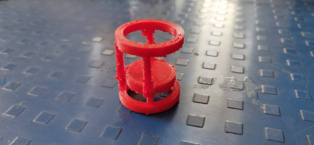
I ended up completely breaking one pillar and also detaching the remaining 3 pillars from the bottom lid of the cage. I wasn’t able to remove
the supports to free the disk from the cage and it still required a lot of cleaning. I then decided to replace the disk with a sphere of the
same diameter
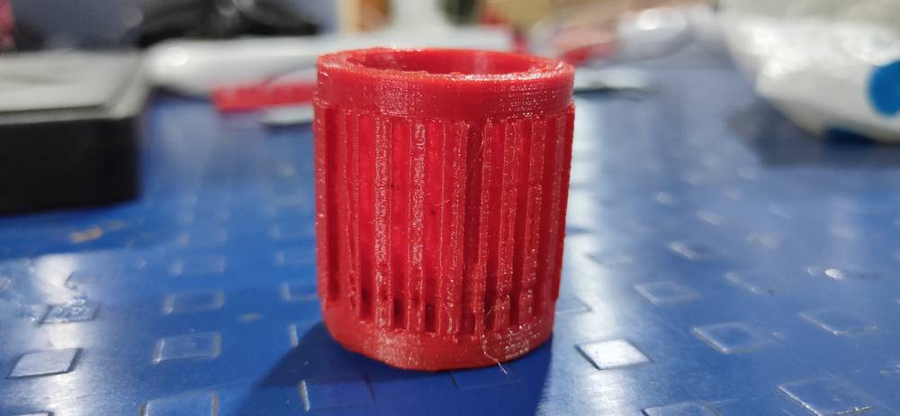
<<<---CAGE AND BALL--->>>
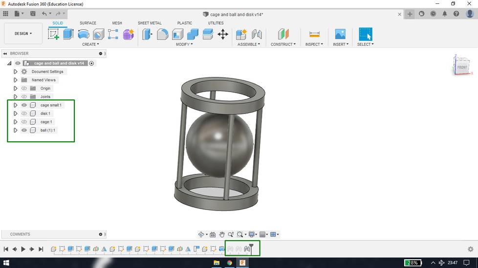
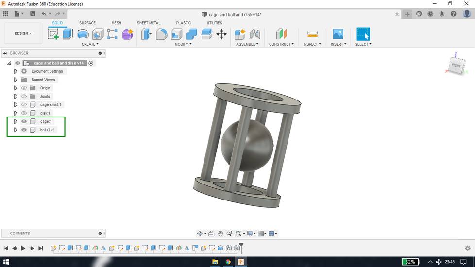
as mentioned above, i kept the dimention of the cage as it was and just changed the disk to sphere of the same diameter,
Pillar length = 40mm
Base thickness 5mm
Ball diameter = 30mm
Slicing. For sicing i’ll be using fracotry from now on
Infill 20%
210° nozzle temperature (i let the software autofill everything except “printing temperature” )
60° bed temperature (i let the software autofill everything except “build temperature”)
Support density 4%
Support pattern line
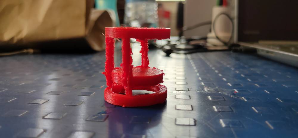
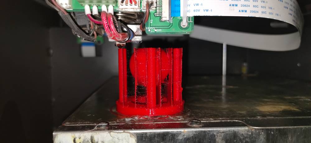
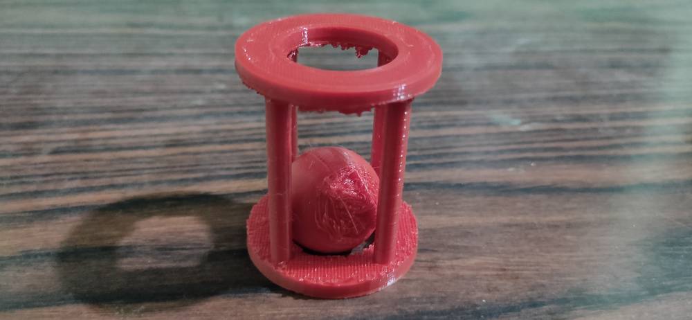
here are the results,
Problems with this model,
stringing
Even with 210° nozzle temperature, there was a lot of stringing in between the model
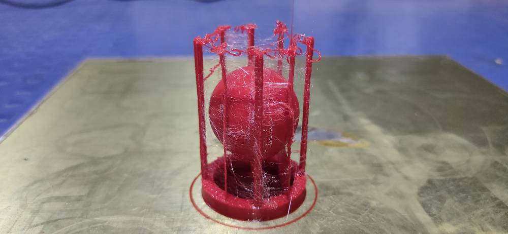
Top layer wasn’t able to bridge
Considering that the diameter between the pillar was 32mm and there were supports generated, the printer wasn’t able to bridge the filament
between the supports and pillar and so the top layer wasn’t able to print.
Pillar broke off
The pillars didn’t merge well with the bottom lid of the cage and so it broke off without any significant pressure
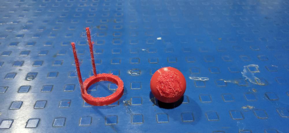
Shape of the ball
Shape of the ball was distorted from the bottom. Either the printer wasn’t able to print the initial layer of the ball or the support was too
much glued to the ball and I wasn't able to remove them.
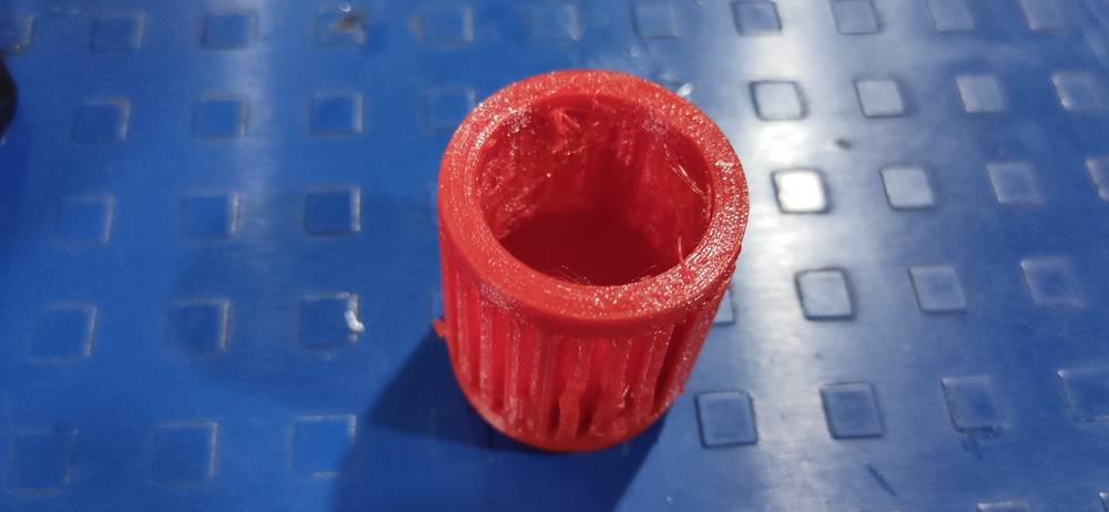
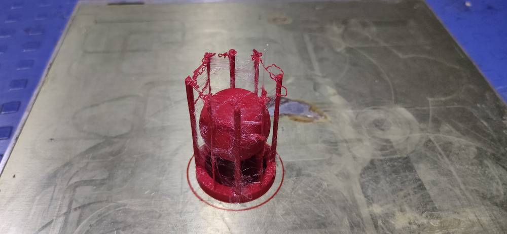
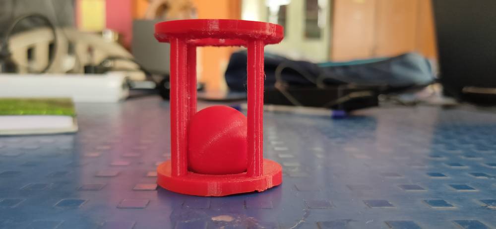
<<<---CAGE AND BALL V2--->>>
Considering the model that i printed earlier, i made some changes in design line change the position and diameter of pillar and in the slicing
I changed the temperature to 200°, support density to 5% and infil to 30%
Slicing,
Infill 30%
Nozzle temperature 200° (initial and final)
Build plate temperature 60°(initial and final)
Flow 90 prime time flow 120 initial layer flow 100
Support density 5%
Support pattern lines

Here are the results,


after the print,

Removing the support was not difficult,
After a little cleaning with file and nose plier,

The bottom layer of the upper cage was distorted even after increasing the support density(the number of support layer increased from 5 to 6.
4% density = 5 layer and 5% density = 6 layer) and also the initial layers of the ball was distorted
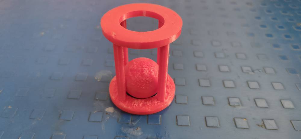
final model,
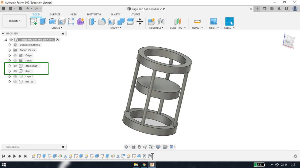
Converting the fusion model into STL file,
For every model i made in fusion, i exported that in STL format and sliced the STL file from fractory. If you have observed earlier, i have
made multiple components in the same file. So if you directly export the file as STL, you will get all the models in STL format in a single
STL file. So if you just want to export few models as STL, what you need to do is orient the model(s) however you wish and hide all the other
components. After that export the file as STL and you’ll only get the STL file of the component which was not hidden.
This model is not possibe to fabricate through manufacturing processes like subtractive and formative. It is only possible to make this
model through additive process-3D printing because this is an object inside an object. Of course, you can re-design in a way where
you make ball and cage separately and then fit the ball inside the cage and glue the base or top plate onto the pillars.
3D Scanning
<<<---SCANNING WITH SCANNER--->>>
For scanning we have a “3D systems sense” 3D scanner in our lab. To use that scanner there is dedicated software “Sense 1” which you need to
install. You can download the sense 1 software from here: https://support.3dsystems.com/s/article/Sense-Scanner?language=en_US
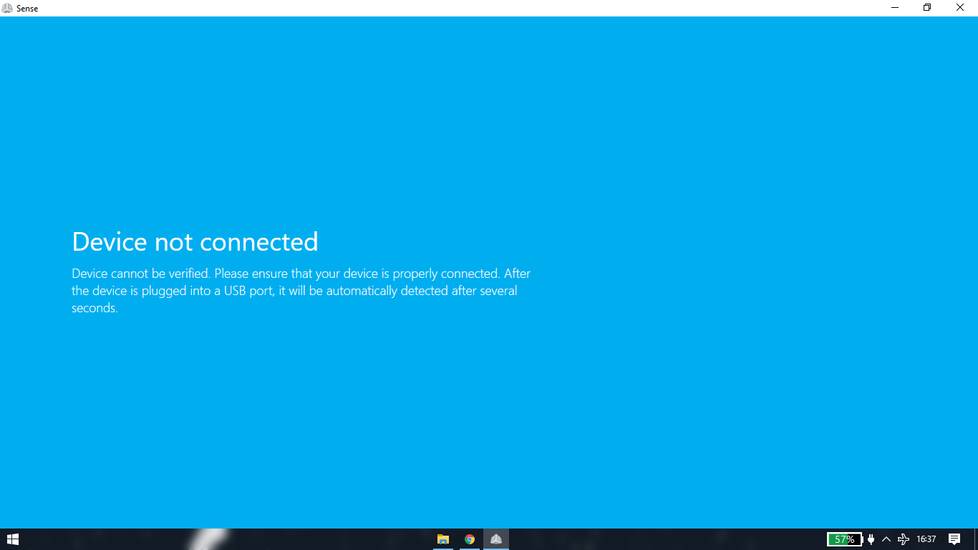
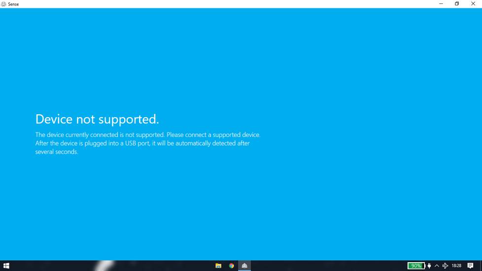
During the installation process, a window pops up asking me if i want to install the software/driver and I accidentally clicked “don’t
install”. I thought the installation would fail, however the installation was completed and i was able to open the software too, but when i
connect the scanner it just wont detect and show error like “device not connected” “device not supported”
I tried to reinstall the software several times, but that window that asks if I want to install the software/driver just won't pop again.
I even deleted the concerned files from the registry editor and install the software again but still that window won't pop again. I don’t even
know what exactly that window was asking to install, but all the other students were able to detect the scanner and only i was not able to
detect so i assumed that it was because of the misclick i did during the installation
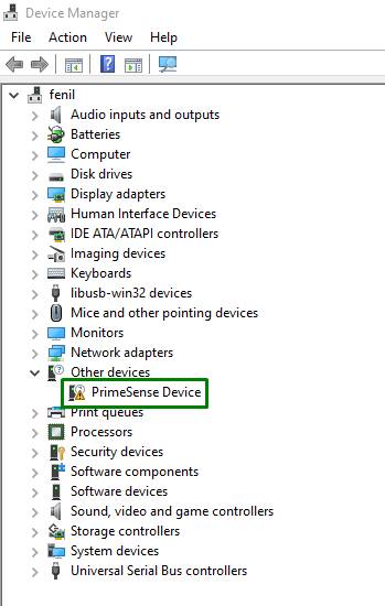
Then a friend of mine suggested to look into the device manager when i plugged the scanner, and sure enough there was some kind of error
showing for “prime sense” driver
So i tried to update the driver by selecting “search automatically for drivers” but the device manager wasn’t able to find any driver online.
So I looked online to see if I can download the driver manually and i come across the website where I downloaded the PrimeSense Sensor
Development Kit 2.x. You can download the driver from
here: https://www.drvhub.net/devices/other-devices/primesense/sensor-development-kit-2-x
After extracting the folder, i again went to device manager and updated the driver by selecting “browse my computer for drivers” and selecting
the path
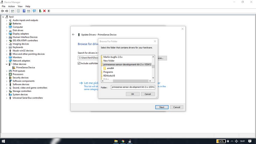

(i guess this was the window that popped up during installation process and i misclicked on “don’t install” but this time i clicked on
“install”)
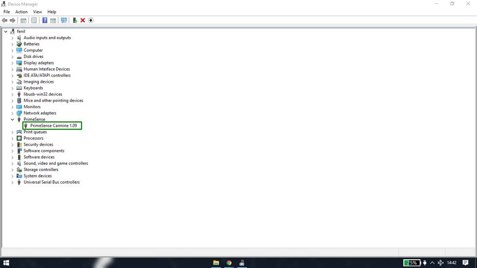
And after opening the software again, it was able to detect the scanner at last
a little introduction about the software
You’ll first need to enter the activation code by selecting the “i have an activation code” from the home screen
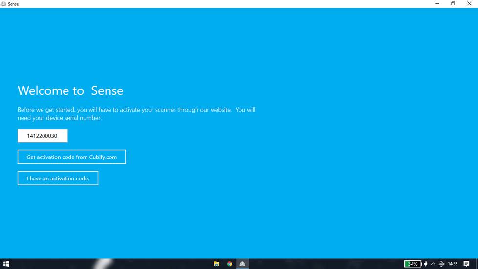
Enter the 4 digit code. The activation code was given to us by our local instructor

The software will ask if you want to scan a “person” or an “object”, select accordingly
Under the object it will ask if you want to scan “small object” “medium object” or “large object”.
After selecting any of the option you'll be able to see the scanner capturing the objects/person around.
Once the object/person is set, click on ”start scan”
Move around the scanner or rotate the object/person to capture every possible angle of the object/person.
Once everything is captured click on pause scan
After pausing the scan select next you’ll get options like crop and erase where you can remove the unwanted objects that were captured and
through solidify you can add some amount of object if the scanner wasn’t able to capture
After clicking on next you will get another set of options like color trim and touchup where you can do minor edits. I haven’t explored that
options though
After clicking on next you’ll get another set of options like save upload and print. Clicking on save option you can save the model in the OBJ
file format, which you can use for slicing in any CAM software. I haven’t explored the upload and print options
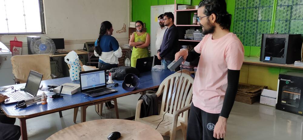
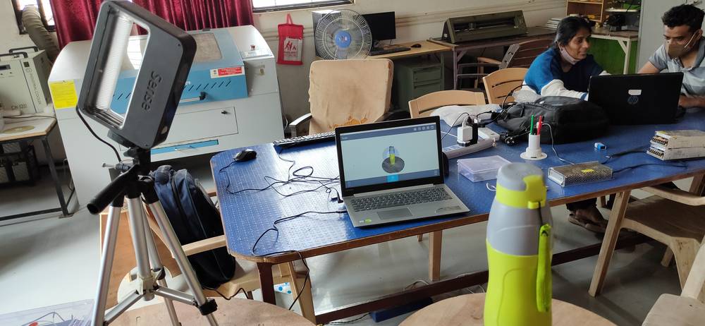
[1] Scanning the person
I helped two of my colleagues scan their faces. I found scanning the person a bit earlier than scanning the object, more on that later.
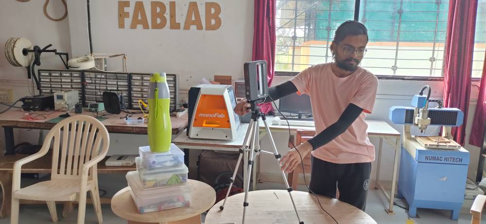
While scanning any object/person you can either keep the scanner stable and rotate the object/person or you can keep the object/person stable
and move the scanner around.
Initially we tried to keep the person stable and move the scanner around, but we were loosing the track after every few seconds so we decided
that we will keep the scanner stable and the person needs to rotate 360° on the same place
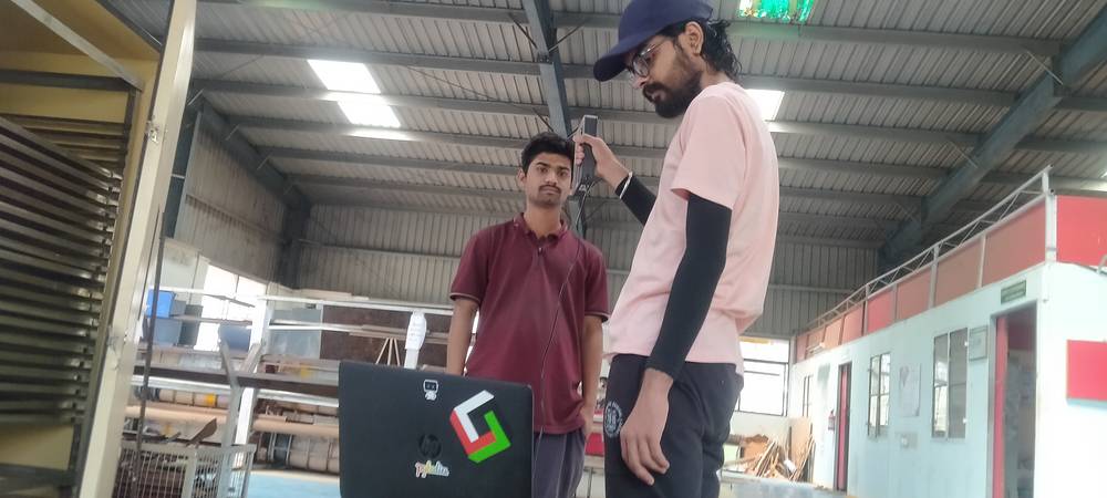

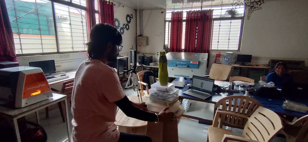
So my colleague just needed to rotate 360° on the same place and I needed to adjust the scanner according to their movement like moving the
scanner back or forth for better focus or move the scanner sideways if the colleague is out of the focus area and instruct them when to start
rotating and when to stop.
The reason why scanning the person is easier than the object is that all you need to do is find a place where there are no objects/people in
close vicinity. The person who wants to get scanned needs to rotate solely and follow the instructions and the person scanning need to adjust
the scanner and give instructions as to when to start and stop rotating.
[2] Scanning the object
I first tried to scan a mouse where the mouse would be stable and I would move around with the scanner scanning the mouse.
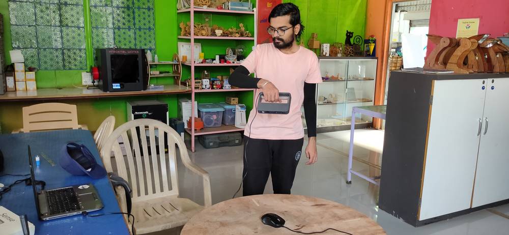
I was getting constant “lost tracing” error if i move the scanner slightly,
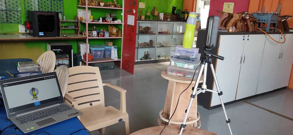
Then i decided change the object to a bottle since it is long and i can put the scanner on the same level then the bottle would act as a
person where not a lot of unwanted objects will be captured. Even if it does capture, i can edit them later. I used my colleague’s laptop
toscan the mouse. It was after that my issue with the software was solved and then i used my laptop to scan the bottle.
Initially i did the same procedure for the bottle where i kept the object stable and move around with scanner but i was again getting the
lost track error
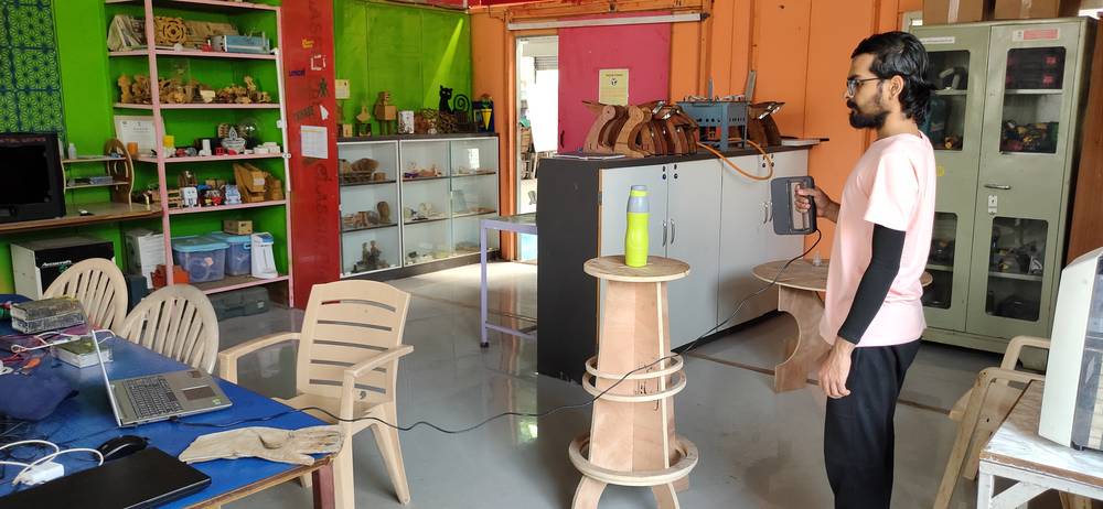
so later i decided to keep the scanner stable and rotate the object.
Raised the bottle for better capturing,
Adjusted the scanner and rotated the bottle,
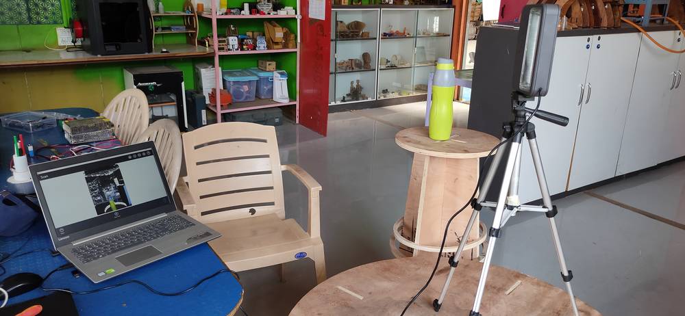
Ultimately i was getting better results without the bottle raised because all i needed to do was crop the table which was captured during the
scanning
I took 3 trials with the scanner being in stable state and i was rotating the table. Here are how the result looked in the first two trials,
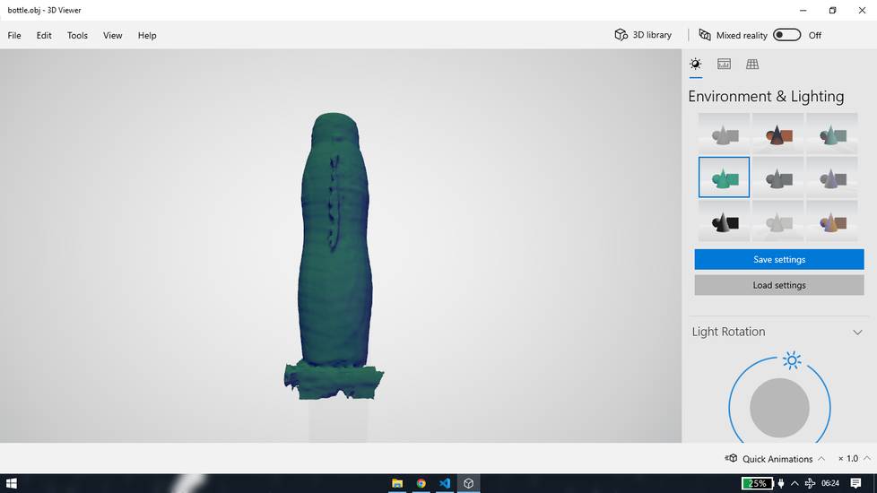
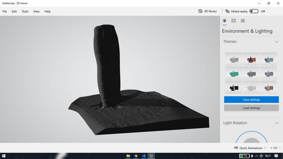
the process is shown in the video linked above. In the third trial the outcome of the scanned bottle was looking better than the first two trial,
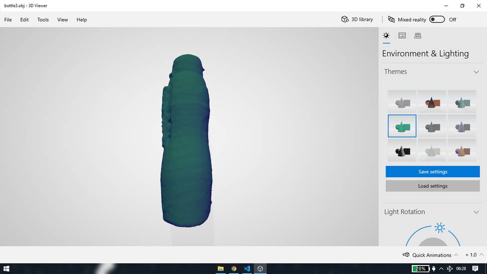
the result was better than the first two trial but not great ebnough for me to 3D print it, so i just saved and kept the OBJ file. You
can download the OBJ file from here: scan file for bottle
<<<---SCANNING WITH MESHROOM--->>>
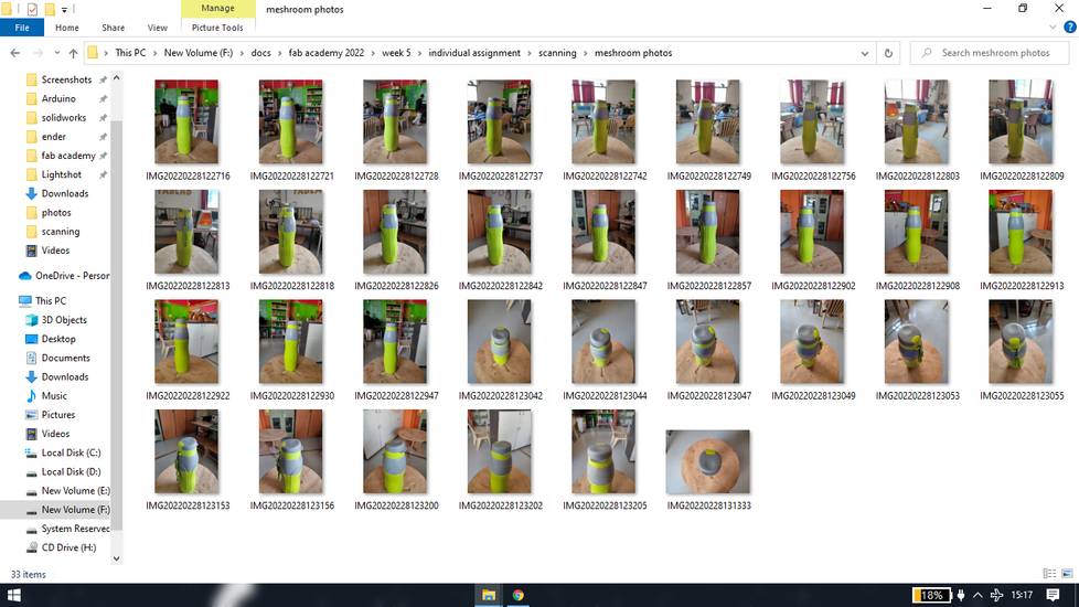
When i was having issue with the sense 1 software i asked in the chat during Global open time and rico suggested to use meshroom and shared
with me a youtube link. I then discovered that meshroom is an open-source software which converts photos into a 3D object. You need to click
pictures of the object from all the angles, the more the pictures the higher the accuracy of the 3D model you will get. So i click the photos
of the bottle from different angles
In the meshroom software you need to save project file first
After saving import all the photos of the object
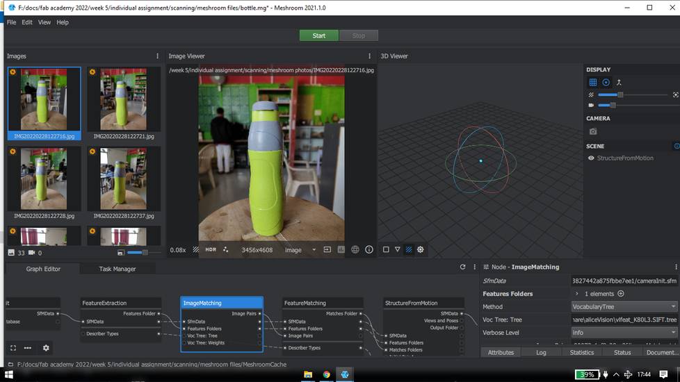
Click on start and you will see the progress bar below the start button and status of each node on the bottom
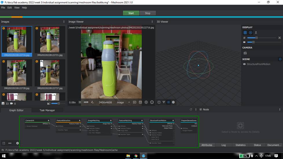
After some time the process would automatically stop on the depth map
I start the process again,
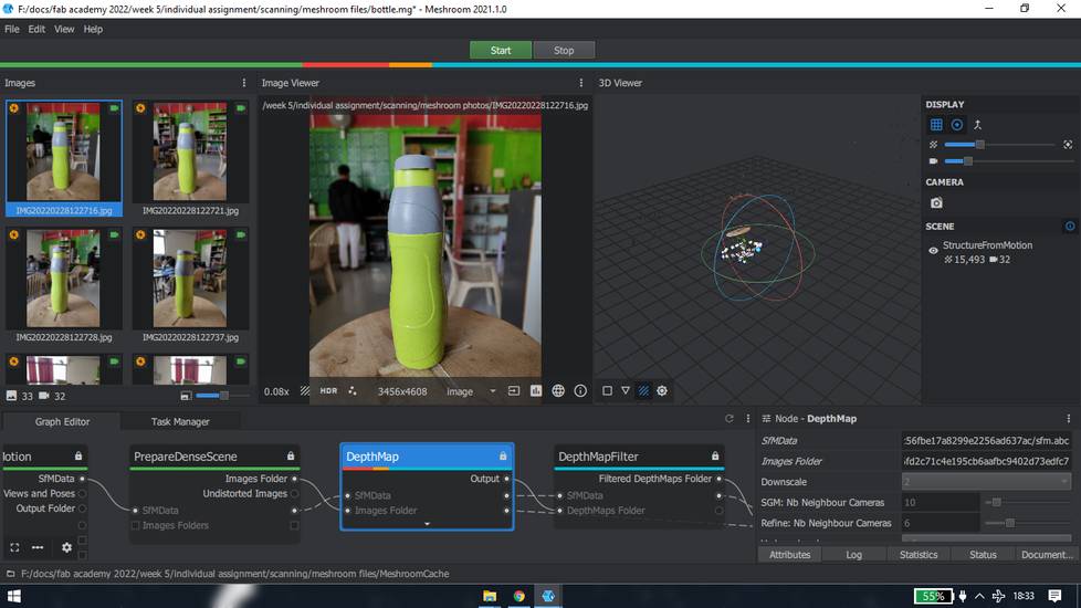
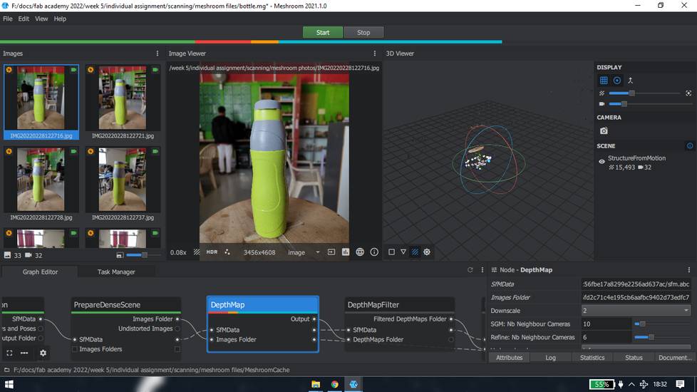
And again after some time the process would stop
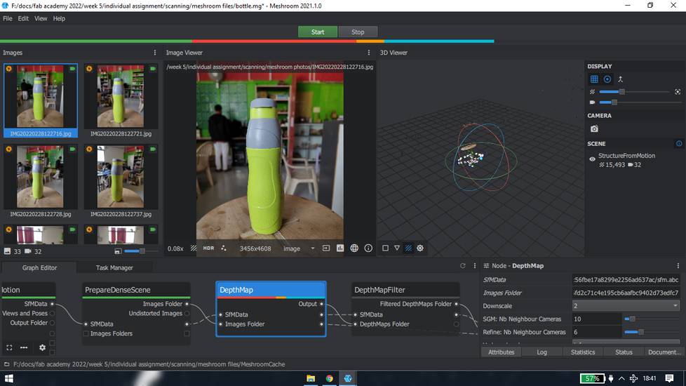
I repeated the process several times but every time the processing would stop on the depth map. Later i gave up on meshroom however i’ll
update the content if i am successful in completing the process of converting photos into a 3d model or if I try any other object.
Edit: 29-06-2022 05:36
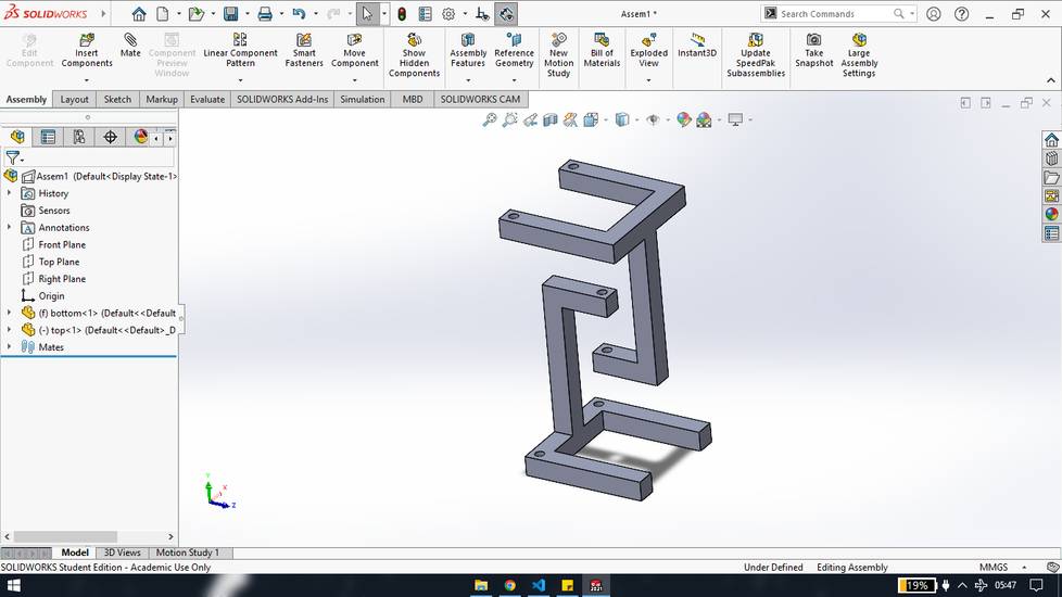
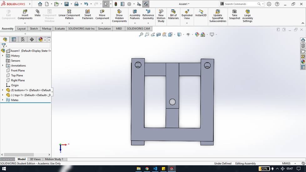
In the week of Computer controlled machining, i had some spare time so i decided to printed and calibrated the tensegrity table.
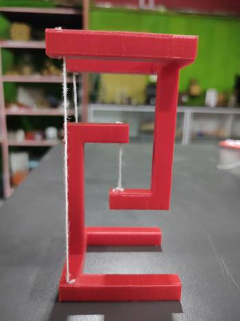
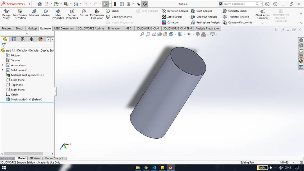
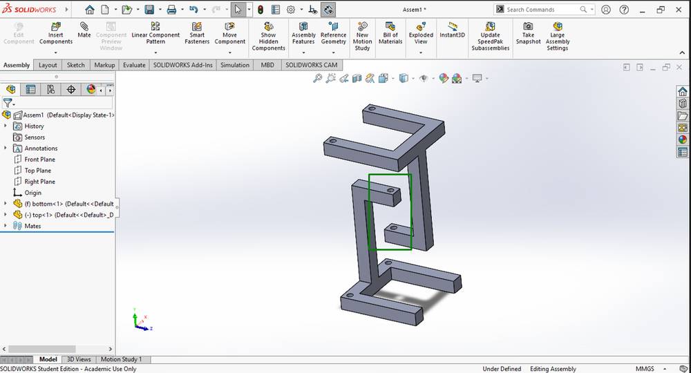
I had designed this table earlier before joining the fab academy. The design of the table is in 3 parts: bottom, top and studs,
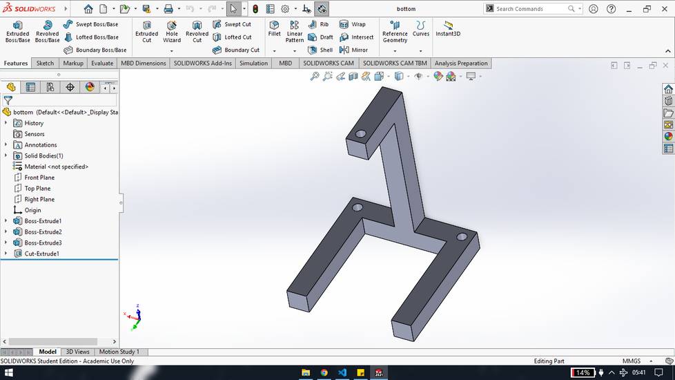
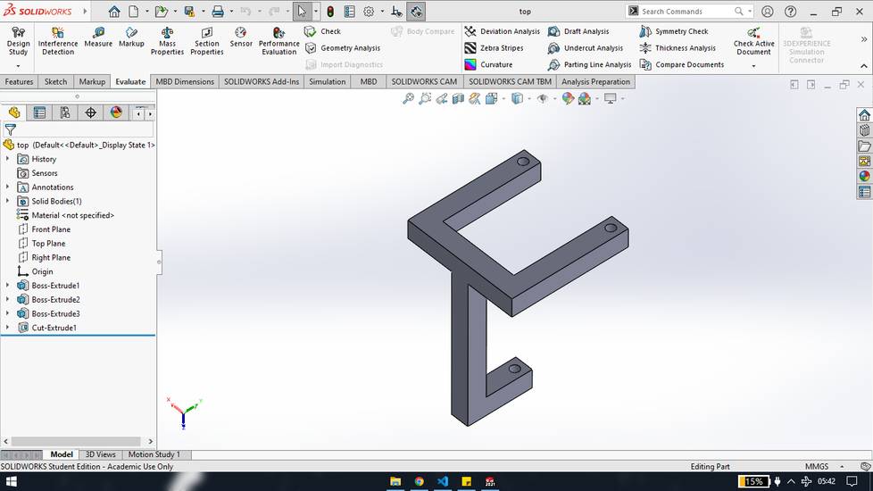
I gave the provision for the holes in a way that the the holes in it's tail is concentric,
The holes in the tensegrity table is to insert the studs. The role of the stud is to lock the thread.
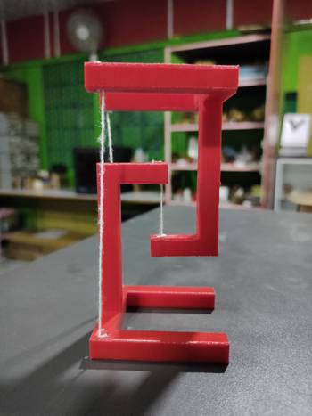
This is how you calibrate the table with thread,
Sand/file your studs for a smooth surface so that the studs can be removed with the screw driver if needed, while calibrating the table,
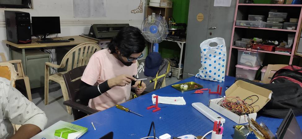
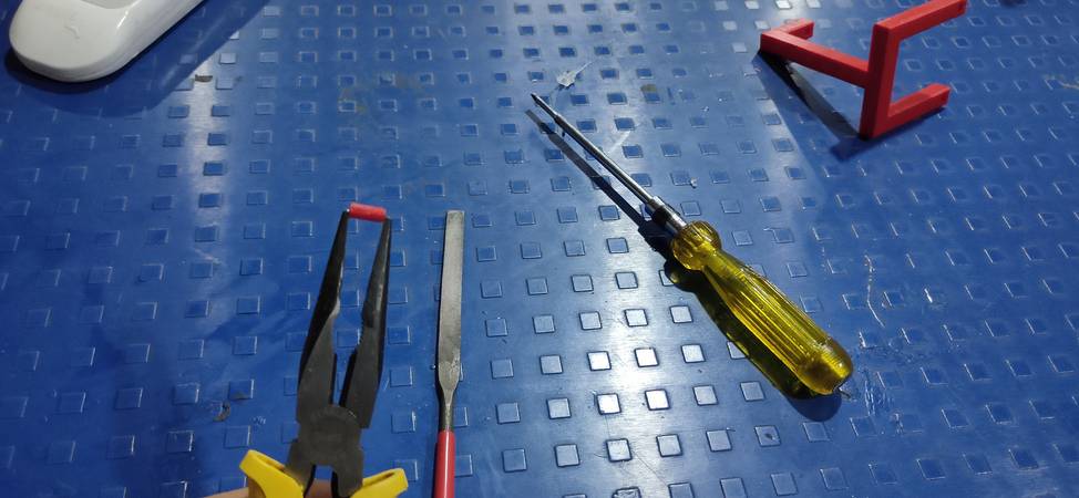
start with these holes,
interwine the thread in the holes and lock them by inserting the stud. For this particular pair of hole, you just need to adjust the height
of the table.
After that do the same with the other two pairs, but lock the thread by inserting the studs on only one side,
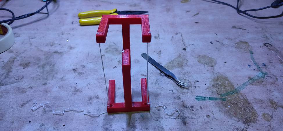
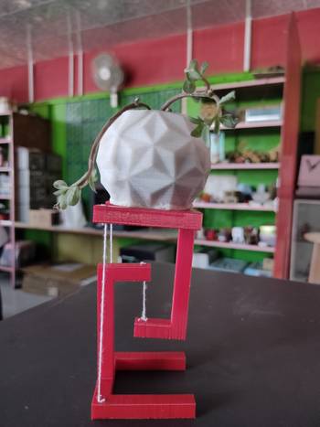
you need to calibrate the table by pulling the string back and forth. If you pull the string too much, the table will fall in front and if you
keep the string loose, the top of the table will remain tilted. If the sting is pulled too much on one side, the top table will keep falling.
So keep tweaking the thread until the top table stops falling and then insert the stud to lock the thread.
You can downlod the STL files of 3D printing here:
cage and ball
tensegrity table
tensegrity table on thingiverse: https://www.thingiverse.com/thing:5330243
You can download the original design files from here:
cage and ball degign
tensegrity table design
Group Assignment
link for group assignment ink: https://fabacademy.org/2022/labs/vigyanashram/groupassig/groupassignment3.html
Drip Irritation by Fenil Chandarana is licensed under Attribution-NonCommercial-NoDerivatives 4.0 International![]()
![]()
![]()
![]()